
ZN414 AND EQUIVALENTS ON SW:
As I mentioned earlier the Internet is the best source for anyone
interested in building a ZN414 type MW receiver. One can easily reach articles, circuit diagrams,datasheets and valuable info using this chip or equivalents. Although some of them are identical, either old or new, many different ideas still exist.
Unfortunately due to the limited cut-off frequency of the ZN414 or equivalents few articles are available regarding SW reception, since above 3MHz is “Area Unknown”, as coverage includes LW,MW and The Tropical Bands only.
Thankfully some curious experimenters have tried to cross the cut-off frequency of the IC to receive broadcasts in the 49Meter Band, which
is between 5900-6200 MHz . There are even circuits but rare, that refer to even much higher frequencies.You have to bear in mind that the performance on SW will not be as efficient as MW since the IC is not designed for such purpose.
Sensitivity and selectivity may not correspond to your expectations but you may tune strong Broadcasts such as VOAmerica, BBC ,Radio China(Beijing), Moscow etc. and several others having multilingual broadcasts, depending upon the area where you live.
The nearest to my area is Radio Bulgaria about 250Kms and VOTurkey (Ankara)450Kms on the 41 meter Band which I can tune both in addition to above.Most of the receivers referred to use an air spaced former, which is
rather bulky and if you are interested even a larger Project Box will
be necessary.
You must also bear in mind that the reception on SW will definitely
require either an external or a telescopic aerial.I made my experiments
with a long wire of 6-7 meters or a telescopic aerial of 65cms ,but plan
to use a longer one of the latter.When using a pair of 32 Ohm phones referred
to below the performance was excellent with some strong broadcasts without even extending the telescopic aerial.
Those of you familiar with SW listening know very well, that reception
on SW depends upon the conditions of Ionosphere.
Due to the limited broadcast time of 1200 kW local MW transmitter ,
which is 3 hours only every morning, I never thought of adding a
stronger and efficient AF Amplifier for loudspeaker use. I decided
to try the SW, since winding such a coil was much easier,require less
time,in addition the waveband seemed more interesting to tune.
I had an efficiently working circuit good for the purpose.
The only adjustment needed was to prepare a coil suitable for SW to receive
the 49 and 41 meter bands . 5900-6200 and 7200-7450MHz respectively .
Both these wavebands are most active after dark.
You can try locals daytime, as I mentioned above about the reception of
both my nearby broadcasts.
At the beginning frequencies as of 31Meter and 25Meter seemed like
an adventure, but my experiments went down to the 25meter band
when I tuned BBC,Radio China,All India Radio and some others.
To begin with I constructed a MW receiver on a testboard .
Winding The Coil,(Alternative One) :
Although my MW receiver has a ferrite slab/bar I started using a
rod of 8.5 cms long and 1 cm diameter. A broken rod from my junkbox.
I knew from my experiments that about 70turns would be sufficient
with a 220pF( 160+60pF) polyvaricon variable using 0.30mm enamelled copper wire to tune the MW. After testing the circuit on MW, I started
to wind a test coil for SW.
At the beginning I used a coil of 30 Turns and I was someplace at the high frequency end of MW. The next step was about 25 turns.No proper
broadcast was heard only faint mains humm.Later 20 turns.Going down to
13 Turns also did not bring much. Until I diminished the number of turns to
9 and I could tune some broadcasts after dark.
I gave a final try and stayed by 7 turns, where I started to tune during noontime the two 41 meter band broadcasts mentioned above.Please note that the 13 , 9 and 7 turn coils were space wound , whereas the former coils were close wound.For a better result I tested several other rods of 10 and 12 cms.
Surprisingly no reception was possible. Rechecking the circuit no bad connection was detected. The moment I started to use the old broken rod the reception quality was as good as before.
I will therefore highly recommend you to test all the ferrite rods you do own before looking someplace else for an error. Unfortunately some rods are not suitable for high frequency use and prove to be convenient for lower frequencies. This may disappoint you with faint or no signals at all on SW Broadcast Bands .
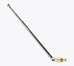
Telescopic
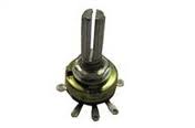
Aerial
Rotary Switch
2.2K Pot with switch
Winding The Coil(Alternative Two):
After testing both with a long wire and telescopic aerial, as mentioned before I decided in favour of the latter to be replaced with a longer one later.
As only one ferrite rod was the most efficient one I also tried a ferrite slab/bar exactly the same type used with the ZN414 MW receiver.
I prepared a coil of 5 turns spaced wound 0.50mm wire.the result was much
much better. Reception was sharper and much stronger.At the beginning all
tests were made with a crystal earpiece.
When I replaced the crystal earpiece with the pair of 32 Ohm EP-50
phones.The volume was much higher, faint signals were louder and audible.
At the cost of a few mA more a pair of 32Ohm phones must definitely be
used and preferably the Creative EP-50.
Volume of some broadcasts is so high more than the level received will
harm the ears. Using a telescopic aerial would enable portable use of the receiver on SW and only with the ferrite slab/bar on MW.If you do not have an air type 365 pF variable you may use alternative one coil with a polyvaricon type same value as above with good results,but the latter one is preferable.
I also tried an air type 406pF variable with similar results but as this is not a standard value the use of 365 pF will be the most suitable for given number of 5 turns.For a wider coverage of SW,You may also prepare a spaced coil of 9 turns. Instead of tapping the coil while winding, first finish the coil and afterwards scrape off the enammel carefully with a small piece of sandpaper about 3mm
from the 5th turn and make an extension by soldering from that point.
Thus you will have in total a 9 turns spaced coil with a tap at 5th turn.
With this coil using the 9 turn leads almost half of the V/C was empty (No signals) this will possibly be around the higher frequency tropical band.A single coil of either 5 or 7 turns without a tap also recommendable as mentioned above.Instead a three pole two way rotary switch a mini switch will also do the job.

Volume Control
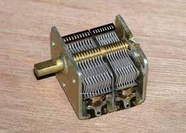
160X60 pF Air Type Variable
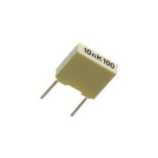
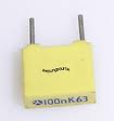
100n Capacitor
10n Capacitor
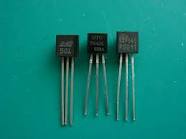
Set of IC's.