
TRANSISTOR SHORT WAVE RECEIVER
After nearly 45 years , I came to the idea of preparing a simple short wave receiver using minimum number of components compared to the one I designed and constructed many years a go.There is no doubt that technology has achieved a lot in the mean time, although the components I used are available since many years however not as old as the germanium transistors which I once used. It is not easily possible for the home constructor to find such simple circuits. I remember as a beginner how many times I was disappointed in the past when searching for a simple circuit,misled by the title.Even today many such circuits exist.When locating the circuit due to the innumerable number of components used, a beginner could easily get lost and fail. In the mean time the number of short wave broadcasts diminished considerably , many are digitalized , which can be tuned by special radio receivers.The task is even difficult when using simple receivers like the one described in this article.In spite of the drawback I was able to tune many broadcasts and obtained QSL Cards for the ones I applied for.There is no need to add that tuning short wave stations is a little tricky and requires some experience like,to know the proper broadcast times on various bands concerned, in addition the Ionospheric conditions which can not be known during the use of a receiver .Last but not least one should also consider the time difference between the broadcast and reception point.Below You will find two links of important webpages regarding the Short Wave Broadcast Schedules which are updated from the server regularly .
The Circuit:
This is a simple 3 transistor regenerative receiver, which consists of one stage of RF and two stages of AF amplification and can tune between 5500 kHz-22.000 kHz which starts before the 49 meter band till including the 13 meter band.As a homemade coil is used the frequency coverage at the high frequency end may go up to 22.000 kHz although sensitivity decreases as the frequency goes much higher.Tuning is achieved in three switching positions and a part of the former part is covered with the next position.I can Tune Radio Kuwait regularly depending upon the Ionospheric conditions at 21540 kHz at good volume.The battery consumption is very low.Needs a 1.5 v AA battery and depending upon the AF transistors it will vary between 1.5-2.5 mA.I forgot the receiver working several overnights and the performance was still at top level.I will recommend You to use quality alkaline batteries. The AF transistors can be found easily . I used a pair of BC548C transistors with higher consumption and two 2N2222A transistors with lower consumption.For the first stage definitely a 2N3904 should be used although it is not an actual RF transistor performed well and can be found easily too.As per my experience the transistors of same identification code had different levels of sensitivity.I will therefore highly recommend You to experiment with different 2N3904 transistors ,if You have several ones of the same type.I had both 2N3904 and some equivalents or substitutions of above and the best performance was when using actual 2N3904 transistors. As all the transistors are NPN type in plastic case, the battery polarity should be set accordingly. Transistors used do not have identical leadouts 2N2222a or the equivalents PN2222a and former P2N2222a.Also a BC548C has different leadouts.The leadouts of a 2N3904 vary compared to the ones too.The circuit has adjustable regeneration control which is made by VR1.This varies the sensitivity thus enable tuning of weaker broadcasts.I have as usual used transistor sockets to prevent the accidental damage of transistors due to excessive heat during soldering.
Compared to the TRF Reflex , a super regenerative circuit is noisier but much sensitive.The emitter of TR1 is connected to the first tap of the coil and not earthed a popular and efficient principle at the time of valve receivers.Please bear in mind that the RF stage of a TRF Reflex circuit first makes a RF amplification than an AF amplification, whereas a regenerative circuit amplifies the RF signals twice.In spite of this capability the performance can never be compared with a superhet circuit.It will however give the enjoyment of tuning SW broadcasts with a self constructed simple receiver; which can receive DX broadcasts too.
The Coil:
As I already mentioned the coil used is a homemade one and easy to prepare.I have prepared two coils on different formers any one of them can be used with equal results.The former I used for the first coil is the plastic roller of cash registers.I was lucky to find several ones from the store nearby free of charge as they are thrown away after use. The first former has a diameter of 1.8cms. The former for the second coil was an old coil former from my junkbox having a diameter of 1.2cms.
a)The first coil (dia 1.8cms)has in total 18 turns taps taken at 1st,3rd,10th , turn .Shortly it reads 1+2+7+8=18 turns. Another variation of this coil can be having a total of 20 Turns.Taps taken at 2nd,4th,12th turn shortly it reads 2+2+8+8=20 turns.
b)The second coil (dia.1.2cms)has in total 23 turns taps taken at 1st,4th,12th, turns .Shortly it reads 1+3+8+11=23 turns .I am using this coil (b) with a VC of 120pF.
For both coils I used 22SWG Magnet Wire.If You have by chance a Radio Shack shop in your area there are triple sets sold in different colors.Copper,Green and Red.The Copper colored is the 22SWG one.This is not a must however, You can surely use any 22 SWG magnet wire.Do not forget to remove the varnish both on coil ends and taps (about ½ cms) for soldering. In case You are using formers of different diameters modifications on the number of turns may be necessary this is also valid in case
of using Variable Capacitors of different values.If You have a twin gang VC You have to use the gang having more slices which means more capacity.Such a VC normally has a value between 160-200pF.
The Antenna:
You have remarked that there are two antennas reflected in the circuit diagram.The circuit uses either a telescopic antenna or an external antenna which is simply a long wire of about 70 cms thrown over the metal radiator slices of the central heating at random.I did not have the chance of using an external aerial but this one performed better than a telescopic antenna as it circulates the entire building.The telescopic antenna will be efficient when nearby or strong broadcast are
concerned.Some broadcasts can even be received without an antenna but this is rare.You may however decide for the long wire alternative. I am using this too.This will also save the cost of the telescopic antenna.The use of metal bedside parts can also be tried as in olden times provided no isolation.The long wire can be connected to the circuit in two ways :
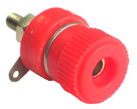
a) With two banana sockets,one connected to the top of the coil(end of the coil) and the other to the last tap, the one before the top coil end.This means to the 10th turn on coil (a) and to the 12th turn on coil (b).
b)You can also use a two way three pole mini switch .The medium lead to the antenna and the top end of the coil to one lead of the switch and the last tap (the one before the coil end )to the other lead of the switch. This will make it easier to connect the antenna to the coil thus simplify the use of the antenna.I did not use this switching alternative due to space shortage on the front panel. I will use this method if I am able to fit everything on the front panel or find a slightly larger project box, as it simplifies a lot.When using the antenna from different banana sockets slight sliding of tuning positions on the VC may be experienced.For the antenna a wire of longer length about 2 meters was also tried not thrown over the radiator slices but on the floor which resulted in sliding of wavelength thus did not perform satisfactorily however this may prove satisfactory in your case.
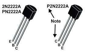
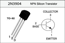

Transistor Lead-Outs .
Banana Socket
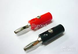
Banana Plugs
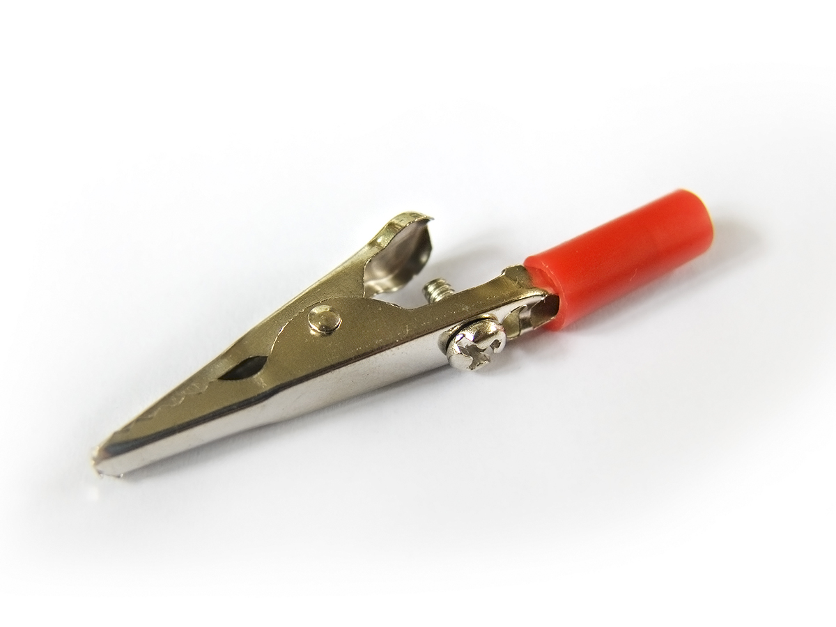
Crocodile Clip

Herewith I would like to thank My Son Danny Sabciyan for drawing the circuit diagram and converting images into site compatible format and to My Friend Geoffrey Brown for modifying the circuit diagram and reviewing the article content.
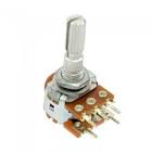
10K Lin. Pot