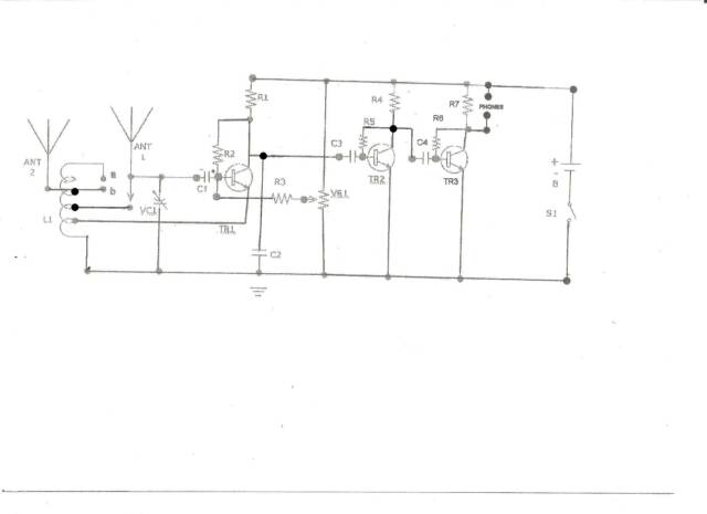
The Circuit Diagram of the Receiver:
As can easily be seen ,the circuit has very little number of components and any beginner can construct.Failing is more difficult than constructing, however enough to perform fine.As in my ZN414 Receiver I used a pair of EP50 , 32 ohm phones of Messrs.Creative in series .With a stereo to mono jack adapter or a crystal earpiece at the cost of lower volume without the jack adapter.You can also try low impedance headphones having a higher value compared to the EP50 earphones.When Using other earphones with higher impedance You may need to remove the 10K collector resistor of TR3 but with a parallel
capacitor between 5N to 10N.This may also result in eliminating the stereo to mono jack adapter as the reason of using the adapter was to increase the impedance of EP50 phones.Also please bear in mind that a pair of magnetic phones of about
2000 Ohm or higher will not be suitable for this receiver due to distorted output.
Components List :
R1,R4,R7 - 10K
R2, - 100K
R5,R6 - 180K
R3 - 33K
VR1 - 10K Lin (B) with Switch
C1 - 10mF Elec.10V
C2 - 10N
C3,C4 - 100N
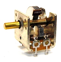
VC1 - 120-180pF Air Type( in combination with a Vernier or reduction drive)
Tr1 - 2N3904
Tr2,3 - 2N2222a or BC548C
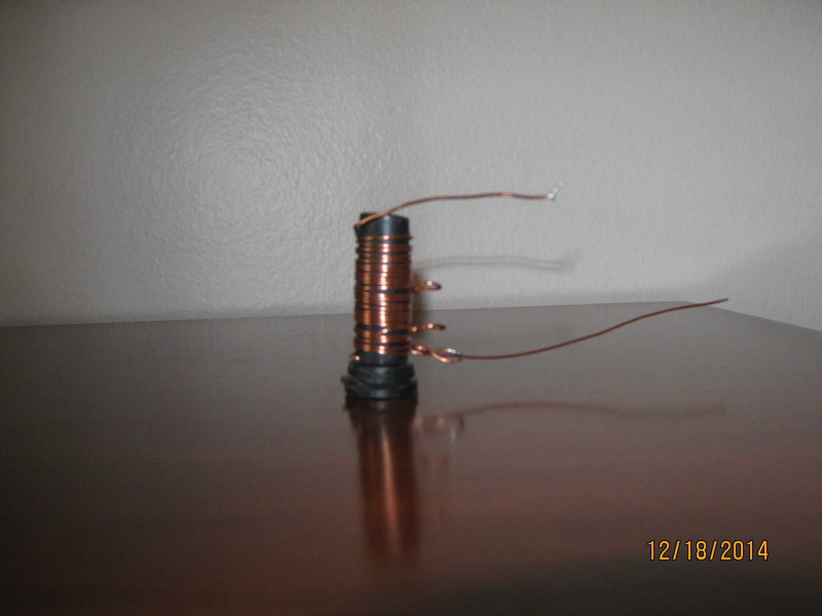
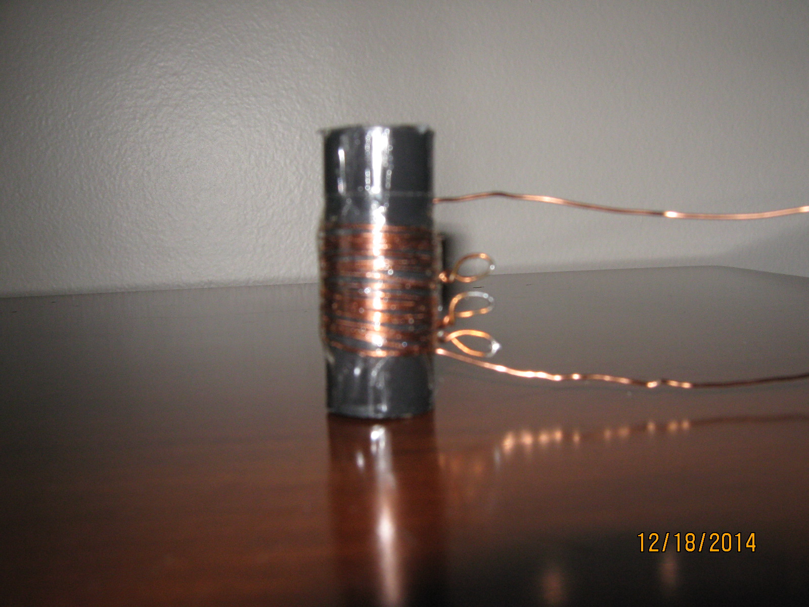
L1 - See Text
B1 - 1.5V AA
Ant. - See text
Misc. - Long Wire,2 Banana Sockets,Banana Plug,Telescopic Antenna, Battery Holder,Transistor Sockets,Rotary Switch(3 Port Two Way),Vernier Drive or Slow Motion, Project Box ,Earphones, Stereo to Mono jack adapter etc.
All Resistor 1/4 Watt
Some Broadcasts Received from My Location( All Distances in Kms):
Radio Kuwait Distance 2150 (Kuwait)
Radio Riyadh “ 3468 (Saudi Arabia )
Islamic Rep. Iran “ 3463 (Transmitter . Sirjan)(Broadcasts also in western languages.)
Radio Romania “ 648 (Galbeni) received QSL Card “ “
Radio Taiwan Int. “ 2869 ( Issoudun, relay in France) waiting for QSL Card
BBC World Svc. “ 7470 ( Meyerton South Africa) received confirmation
All India Radio “ 5634 ( Bangalore ) received QSL Card,applied for a new one
Voice of Turkey “ 453 ( Emirler) (Broadcasts in western languages)
Radio Vaticana “ 1750 ( Vatican City ) Received QSL Card
China Radio Intl. “ 4719 ( Urumqi ) Applied for a QSL Card over a year a go still no reply
Japan Broad. Corp. “ 2394 (Germany )European relay station received QSL Card
In addition I can tune a lot of broadcasts, mostly in Arabic and others which I did not mention as the languages are not familiar to me and could not be identified.Some of a.m. transmissions mentioned above can be tuned regularly however I never applied for a QSL Card . Please note that I am not a QSL Card Hunter therefore I am satisfied with the above unless I can tune something special.
Using The Receiver:
When the construction is over and the receiver is ready for use please check all connections and if there is no short circuit or incorrect connection including battery polarity You may switch on the receiver.You will hear a hissing sound when the VR1 is
at minimum position then You may slowly adjust VR1 to the maximum position meaning minimum resistance until it reaches the oscillation point.Here You will be able to tune broadcasts if the volume is low try to increase the VR1 position to maximum ands further broadcasts will be audible. If the oscillation is severe and the broadcast is not received clearly You may lower the level.After sometime depending upon the frequency of use You may have trouble with the reception quality hearing whistles or cracking sounds which means that the VR1 has to be replaced with a new one.. Unfortunately the quality of Potentiometers are rather poor nowdays as You have to play back and forth to adjust sensistivity this will end the life of this component earlier.
DEAR VISITORS !!!THE CIRCUIT DIAGRAM IN THE CURRENT FORM IS COMPLETE AND ALL DETAILS ARE FULLY REFLECTED.UNFORTUNATELY DUE TO RESOLUTION PROBLEMS SAVING OF THE IMAGE IS NOT AS DARK AS IT SHOULD BE. I HOPE TO REPLACE THE DIAGRAM WITH A CLEARER ONE IN DUE TIME . I APPRECIATE YOUR UNDERSTANDING.
Coil * A *
.
120 pF VC
Coil * B *

180K Resistors
10 N Capacitor