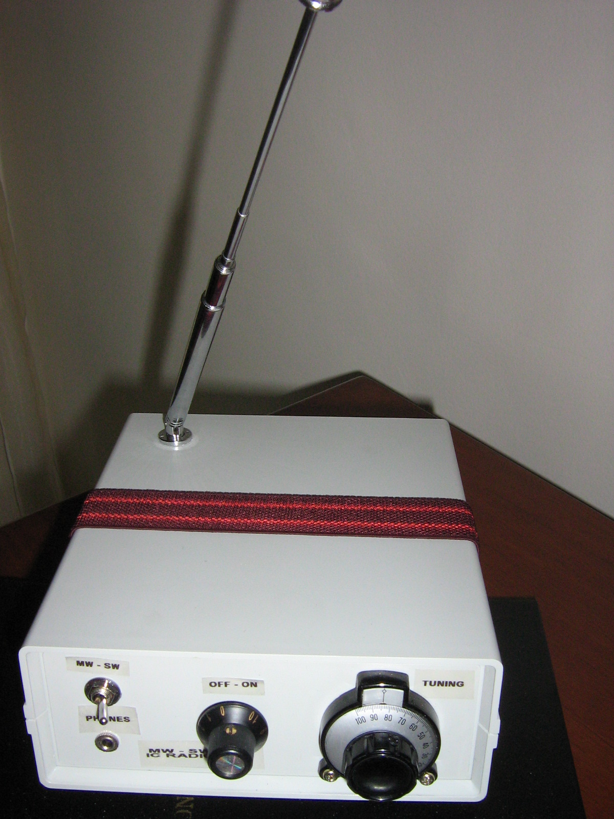
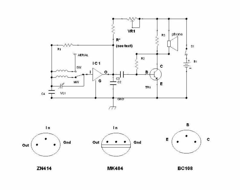
Below is the circuit diagram .As You easily remark there is no major change except the coils and
the switch ,which is the former on/off switch now acting for bandchange . The S1 in series with the battery is the switch on 5K pot.
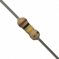
10K Resistor
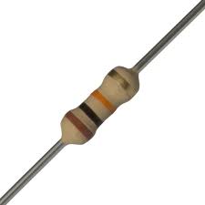
100K Resistor
A G B
G = GROUND
A + G = 60 pF
B + G = 160 pF
A + B and G = 220 pF
Above are the details of 160+60 Pf Polyvaricon Variable lead connections
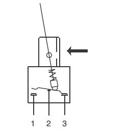
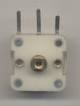
Mini Wavechange Switch
Pole (1) is connected to SW Coil and Telescopic Aerial.
Pole ( 2) is the middle lead and connected to the Input (I) of IC. and VC1
Pole ( 3) is connected to MW Coil.
Pole (1) and (3) can be interchanged as per Your Wish
SOME LINKS TO SW CIRCUITS RELATED TO ZN414 OR EQUIV ALENTS :
A ZN414 SW Receiver by Andy Collinson.
A MK484 SW RADIO by Tom Merryfield
A Toroidal Core ZN414 TRF SW and a collection of other Two Wave
( MW and LW ) Receivers(some are already reflected under other links)
3 Band( 2 SW + MW ) Radio using LMF501T
The last of above articles is in Japanese but translation regarding info and coil details can be made by Online Bing or alternative translator.
Volume Control